|
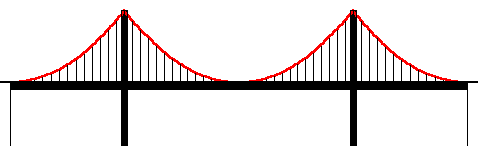
Take a flexible chain of uniform linear mass density. Suspend it from the two ends. What is the curve formed by the chain? Galileo Galilei said that it was a parabola, and perhaps you made the same guess. This time Galileo was not correct. The curve is called a catenary. However, it is easy to see how he could arrive at this answer through casual observation and incomplete deduction. Look at the similarities between a parabola and the curve of the chain. For this comparison, assume that the parabola is concave upward. Both curves have a single low point. They both have a vertical line of symmetry. They at least appear to be continuous and differentiable throughout. The slope is steeper as we move away from the low point, but it never becomes vertical. We can get back to the chain solution later. First consider this extension. What about the curve formed by the cables of a suspension bridge? Is it too a catenary? No, it is a parabola. So, what gives? How can this be a parabola while the other one is not? The ParabolaIt may be more easy to understand these curves if we determine what it is that makes them different. What makes them curve in the first place? In the case of the chain, it is curving because of its own weight. But here is where the bridge cable is different. It too curves under its own weight, but a much greater influence is the weight of the bridge deck. The source and magnitude of the weight is not important, but its distribution makes a big difference.
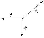
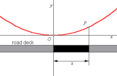
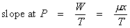
Look at this sketch, and consider the distribution of the mass on a suspension bridge. The road deck hangs on vertical cables suspended from the main cables. The cables themselves may be large, but their mass is insignificant when compared with that of the deck, so disregard the mass of the cable. Suppose that the deck is horizontal, and suppose that its cross section is uniform throughout the length of the bridge. Also, the vertical cables are so close together that we can assume that the weight of any part of the deck is transferred to the part of the main cable directly above it. These conditions are reasonably close to the real thing. Rather than compute the height of the cable at a given point, let us try to determine the slope of the cable at that point. Naturally, the cable will align itself with the direction of the forces pulling on it. There is one point on this cable where that direction is easy to see. At the lowest point, the vertex, the cable is horizontal. Label that point O and let that be the origin of a set of coordinate axes. Now pick an arbitrary point, P, on the cable, somewhere to the right of O. What is the direction of the tension at point P? How do we determine that? Consider only that part of the cable in the interval between O and P. It is motionless. More importantly, it is not accelerating. That means that the net force on it is zero. In the study of physics, forces may be modeled with a free body diagram. Each force is identified with a vector arrow. The direction of the arrow is parallel to the direction of the force, and the length of the arrow is proportional to the magnitude of the force. There are three forces acting on the cable interval OP. One force
is the tension from the cable to the left. Call this force
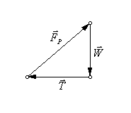
The net force can be determined by adding the vectors. Graphically,
this is accomplished by aligning the vectors point to tail. We already
know that the net force is zero, so the last vector must end where the
first one began. By doing this in the illustration on the right, we can
see the direction of
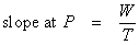
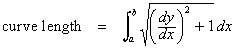
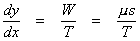
In this equation W and T are magnitudes only, not vectors. But what are W and T? Well, T is clearly a constant. It is the tension at point O, which is the same no matter what point is chosen for P. W is the weight on the cable between O and P. This is the weight of the roadway directly below that length of cable. How can it be determined?
Remember that one of our conditions was that the deck has a uniform cross section throughout. That means that one meter of road on one part of the bridge would have to weigh the same as one meter of road on any other part of the bridge. Let μ represent the linear weight density of the deck. That is, multiplying μ by the length of any interval on the deck will give the weight of that interval. So what is the length of the road from O to P? It is not
the distance between those two points. The cable is curved, but the road
below it runs horizontally. The length of that stretch of road is simply
the difference in the x-coordinates of those points. Point O is
the origin, so all we need is the W = μx
This is where the calculus begins. Let y be the height of the cable. The slope of the cable then must be the first derivative of y.
So y is an antiderivative of the function μx/T.
We know that the origin is on the curve. Substituting zero for x
and y and solving for C, we find that
Since μ/(2T) is a constant, this is a quadratic equation, a parabola. The CatenarySo why does this not work for the chain, which carries no load? Well,
this turns out to be more complicated. We can define points O and
P on the chain, just as we did with the bridge cable. We can even
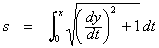
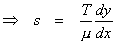
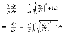
use the same free body diagram, and we get the same slope formula: As before, let the low point of the chain be the origin. Let y be the height of the chain. Again, μ will represent linear weight density. This time it is weight per length of chain. Let s be the length of the chain between O and P. This means that the weight of the chain between O and P must be μs. You may recall this formula for the length of a curve on the interval
We can use it to find s, the curve length on the interval
The derivative, dy/dx, is itself a function of s.
Make this substitution for s in the integration equation above.
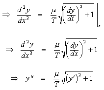
Differentiate both sides with respect to x.
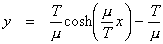
We need to define y as a function of x, so that it satisfies
this equation and the condition
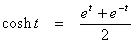
In case you are unfamiliar with hyperbolic trigonometry, the hyperbolic cosine is defined by this formula:
Don’t take my word for it. Confirm that this catenary equation works. Even if you have never worked with hyperbolic trigonometry, you can apply elementary differential calculus skills to find the first and second derivatives of the function. This solution was not actually derived here but there is enough information to verify it. One question remains unanswered. Why did Galileo believe that the catenary was a parabola? Mathematics aside, it would have been quite simple to test it experimentally. Plot a parabola and try to make a hanging chain fit the curve. It will not work. Try it. Click the image below to see a camparison of four curves. The red one is a geometric construction of a hanging chain based on the forces that were described above. The slope of each link has a linear relationship with the number of links between there and the center. The blue curve is a catenary. The green curve is a parabola. Finally, we have the real thing, a photograph of my watch chain. The corresponding sliders control the length of the red links, the weight of the links, and the parameters for the parabola and catenary. At the vertex of each curve is a point that allows it to be dragged. Lay them over the photo and over each other. The parabola will not fit with anything, but the other three fit quite well. The image below is dynamic. Drag the points to see the relationships. Web Sketchpad FilesThe animated sketch on this page was created with Web Sketchpad, a developmental version of The Geometer’s Sketchpad. Copyright © 2015 KCP Technologies, a McGraw-Hill Education Company. All rights reserved.
Geometer’s Sketchpad FileThe animation was created with the Geometer’s Sketchpad (version 4). The original Sketchpad file may be downloaded here: Back to Whistler Alley Mathematics Last update: March 16, 2016 ... Paul Kunkel whistling@whistleralley.com For email to reach me, the word geometry must appear in the body of the message. |